This tutorial explains what slide potentiometers (also called slide pots) are and teaches how you can use them with an Arduino microcontroller to control something. Here, as an example, the number of LEDs of a WS2812b-based LED strip will be controlled. The example is similar to sound mixers and music decks where sliders are used to control e.g. the volume. Sometimes, they give an additional visual feedback of the slider position by the use of a small bar with LEDs.
Material
Components
Slide potentiometer / Slide pots
Slide potentiometers come with many names: potentiometer sliders, volume sliders, mixer, fader, and so on. From a technical perspective, slide potentiometers are just slide knobs that adjust a potentiometer by changing the knobs position. Then, the potentiometer changes a voltage level of the signal that is bound to an output pin. This signal can be used by the analog-to-digital converters of an Arduino (=analog pins) to use the position in an Arduino program.
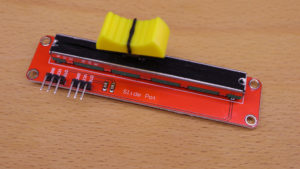
Slide Pot is the name of a very common module that can easily be used with an Arduino. The typical use case for a slide pot is 1) to position the slide knob, 2) use an Arduino to retrieve a signal that corresponds to the knob position, and then, 3) let the Arduino control something. Typically, the slide pot module comes with a red PCB, a slider/fader knob that adjusts a potentiometer, and pins for two data outputs. The slide pot is available in different variants. My variant has also two data outputs but they are on the same wire. As a result, it is not possible to ‘configure’ two different types of output signals with my variant. This is indicated by the pin labels of my slide pot. Both of my signal pins are labeled with ‘DTB’ (Data B). Other variants have two different labels for the signal pins: ‘DTA’ and ‘DTB’ (Data A and Data B). In this tutorial, we need only one signal from the slider. Therefore, the use of the second signal output is not addressed at all in this tutorial!
LED strip (WS2812B)
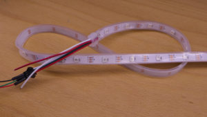
As the name suggests LED strips / stripes are strips with a specific number of LEDs on them. There exist tons of different types of LED strips. In this tutorial we make use of WS2812B LED strips. These LED strips are fully controllable: Every single LED on the strip can be switched on or off. Moreover, the color is also fully controllable as the WS2812B is a so-called “RGB LED” chip.
I already made a tutorial on how to use WS2812B-based LED strips. With the knowledge you gain by this tutorial, it should be easily possible to control also other LED chips or LED components, such as LED rings. If you plan to use LED rings, have a look at my WS2813 LED ring tutorial.
Part I: Slide Pot Basics
The first part of the tutorial explains some basic aspects about the slide pot. The goal is to retrieve the slide knob position and to print it out on the serial monitor of the Arduino IDE.
An output of the slide pot has three pins: GND, VCC and DTB. GND is connected with ground. VCC is connected to the voltage signal. My slide pot does not indicate which voltage levels are supported on VCC. However, voltage levels of 3.3V and 5V are possible for sure. I would be careful with higher voltage levels. Keep in mind, working with voltage levels of higher than 5V might damage your Arduino permanently if a wrong wiring is applied.
The signal pin DTB has a voltage level that corresponds to the slider knob position and depends on the voltage level of VCC. For example, if VCC has 5V, the voltage levels look like this:
- DTB = 0V on the most outer left position
- DTB = 2.5V on the middle position
- DTB = 5V on the most outer right position
So, the most outer right position is always equal to the voltage level of VCC.
The Arduino’s analog pins are able to read voltage levels up to 5V by a so-called analog-to-digital converter. As a result, the analog value will be available as digital values in the Arduino program. The digital values range from 0 (for 0V at analog pin) to 1023 (for 5V at analog pin).
Wiring
The following wiring picture shows the most basic wiring for the slide pot modules. For GND and VCC, the Arduino’s GND and 5V pins are used. The slide pot’s signal pin is wired to the Arduino’s analog pin A0.
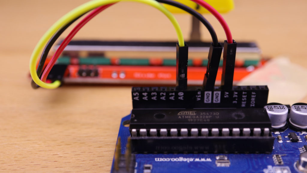
Programming
In the setup function, the serial connection is started to print the values on the serial monitor. Moreover, the analog input A0 is set to input-mode. In the loop function, the current value of slide knob is read, and then, printed out to the serial monitor.
/*
MIT License
Copyright 2020 Michael Schoeffler (https://www.mschoeffler.de)
Permission is hereby granted, free of charge, to any person obtaining a copy of this software and associated documentation files (the "Software"), to deal in the Software without restriction, including without limitation the rights to use, copy, modify, merge, publish, distribute, sublicense, and/or sell copies of the Software, and to permit persons to whom the Software is furnished to do so, subject to the following conditions:
The above copyright notice and this permission notice shall be included in all copies or substantial portions of the Software.
THE SOFTWARE IS PROVIDED "AS IS", WITHOUT WARRANTY OF ANY KIND, EXPRESS OR IMPLIED, INCLUDING BUT NOT LIMITED TO THE WARRANTIES OF MERCHANTABILITY, FITNESS FOR A PARTICULAR PURPOSE AND NONINFRINGEMENT. IN NO EVENT SHALL THE AUTHORS OR COPYRIGHT HOLDERS BE LIABLE FOR ANY CLAIM, DAMAGES OR OTHER LIABILITY, WHETHER IN AN ACTION OF CONTRACT, TORT OR OTHERWISE, ARISING FROM, OUT OF OR IN CONNECTION WITH THE SOFTWARE OR THE USE OR OTHER DEALINGS IN THE SOFTWARE.
*/

/*
 * This is a simple example program on how to use slide pot modules with an Arduino.
 * The program reads the current slide knob position and prints it out to the serial monitor.
 */

#define PIN_SLIDE_POT_A A0


void setup() {
  Serial.begin(9600);
  pinMode(PIN_SLIDE_POT_A, INPUT );
}

void loop() {
  int value_slide_pot_a = analogRead(PIN_SLIDE_POT_A);
  Serial.print("Slide Pot value: ");
  Serial.println(value_slide_pot_a);
}
Application (VCC = 5V)
If everything is wired correctly and the program has been transferred to the Arduino, the program starts to run and shows the slide knob values on the serial monitor. If the slide knob is on a position within the ‘right area’, the value is around 981 (see previous wiring image for used knob position):

The most outer right position will result in a value of 1023.
Application (VCC = 3.3V)
Let’s change the slide pot’s VCC pin to 3.3V.
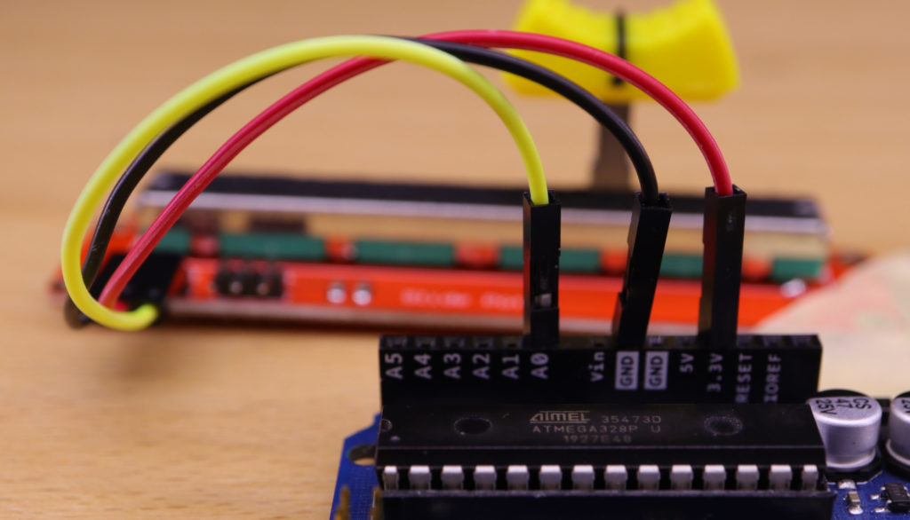
As a result, the maximum voltage level for DTB is 3.3V. As the Arduino’s analog-to-digital converter works within the range of 0V to 5V, the same slide knob position will result in a lower value in the Arduino code. If you run the program again with 3.3V on VCC, you will see that the value for the same position is around 654:

With this setup, the most outer right position will result in a value of around 700.
Application (VCC = not connected, pin mode = INPUT_PULLUP)
If you run out of the 3.3V and 5V pins on the Arduino, you can also use the slide pot without connecting VCC to a voltage level:
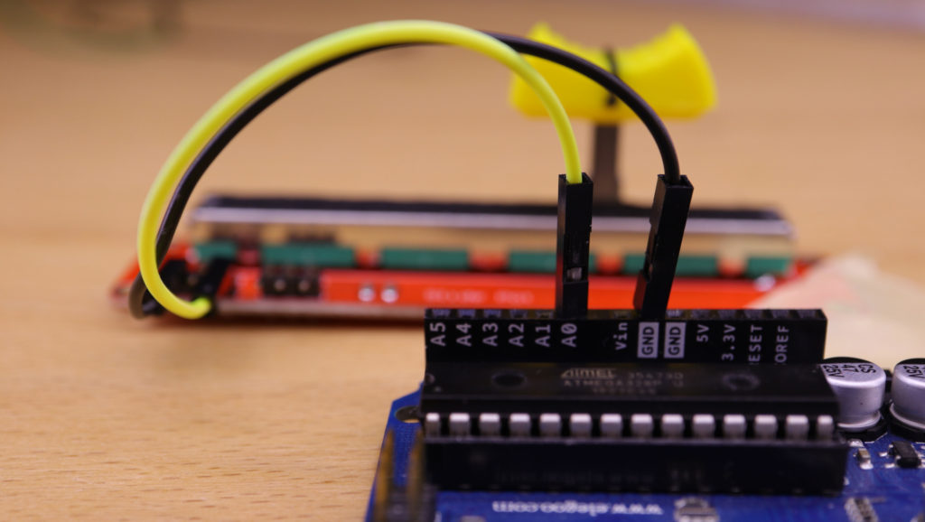
On programming level, you have to change the pin mode from INPUT to INPUT_PULLUP.
...
pinMode(PIN_SLIDE_POT_A, INPUT_PULLUP);
...
In this mode, an internal pull-up resistor becomes active. As a result, we are still able to get the the knob position. However, as you can see. The resolution becomes even lower than with 3.3V. The same position results in a value of about 133:

With this setup, the most outer right position will result in a value of 134. If you are wondering, why the value for the most outer right position is not higher, the reason is that the values are not linearly distributed. On my setup, if I use the pullup mode, the maximum number is already retrieved, if the knob is moved to the middle. Depending on your use case, you might have to implement some optimizations, if you require a perfectly linear distribution of the value range.
Part II: Controlling the WS2812B LED strip
Next, we will use the knowledge we gathered so far and use it to extend our program to control a WS2812B LED strip.
Wiring
In addition to the previous wiring, we have to wire the LED strip to the Arduino. Three wires are required for the LED strip: GND, +5V, and SIG. As the name of the strip’s ‘+5V’ pin indicates, the LED strip requires 5V. Unfortunately, the Arduino has only a single 5V pin which can either be used for the slide pot or the LED strip. Luckily, we know that the slide Pot can also work with 3.3V or even without a voltage level. Here, we go for the 3.3V alternative and wire the slide Pot’s VCC pin to the Arduino’s 3.3V pin:
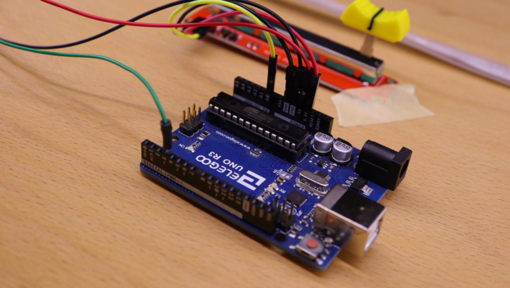
Programming
As I wrote already a tutorial about the WS2812B, I will not explain the WS2812B-related lines of code in detail. In order to relate the slide knob position to the number of LEDs to be switched on, it is important to define the maximum analog value (MAX_SLIDE_POT_ANALGOG_READ_VALUE) and number of LEDs (NUM_LEDS). These maximum values define the upper limits of the ‘analog input range’ and ‘LED range’. The remaining part, such as initializing FastLED, is just basic code which can be looked up in my previous tutorial.
In the loop function, three processing steps are executed:
- The current slide knob position value is read.
- The position value is mapped from the ‘analog input range’ to ‘LED range’. The result of the map function corresponds to the LEDs that must be switched on. If you have never worked before with the map function, have a look at the official documentation.
- Switch on LEDs that correspond to the area left of the slide knob, and switch off LEDs that correspond to the area right of the slide knob.
In the following source code, I set the number of LEDs to 10 although my LED strip has more LEDs. The reason is that an LED strip draws a lot of current and the 5V pin is typically limited to 400mA. If you plan to switch on a lot of LEDs, you require an external power supply.
/*
MIT License
Copyright 2020 Michael Schoeffler (https://www.mschoeffler.de)
Permission is hereby granted, free of charge, to any person obtaining a copy of this software and associated documentation files (the "Software"), to deal in the Software without restriction, including without limitation the rights to use, copy, modify, merge, publish, distribute, sublicense, and/or sell copies of the Software, and to permit persons to whom the Software is furnished to do so, subject to the following conditions:
The above copyright notice and this permission notice shall be included in all copies or substantial portions of the Software.
THE SOFTWARE IS PROVIDED "AS IS", WITHOUT WARRANTY OF ANY KIND, EXPRESS OR IMPLIED, INCLUDING BUT NOT LIMITED TO THE WARRANTIES OF MERCHANTABILITY, FITNESS FOR A PARTICULAR PURPOSE AND NONINFRINGEMENT. IN NO EVENT SHALL THE AUTHORS OR COPYRIGHT HOLDERS BE LIABLE FOR ANY CLAIM, DAMAGES OR OTHER LIABILITY, WHETHER IN AN ACTION OF CONTRACT, TORT OR OTHERWISE, ARISING FROM, OUT OF OR IN CONNECTION WITH THE SOFTWARE OR THE USE OR OTHER DEALINGS IN THE SOFTWARE.
*/

/*
 * This is a simple example program on how to use slide pot modules with an Arduino.
 * In particular, tis programs shows how to control an WS2812B LED strip with a slide pot input.
 */

#include "FastLED.h"

#define PIN_SLIDE_POT_A A0 // input pin of the slide pot
#define MAX_SLIDE_POT_ANALGOG_READ_VALUE 700 // maximum voltage as analog-to-digital converted value, depends on the voltage level of the VCC pin. Examples: 5V = 1023; 3.3V ~700

#define NUM_LEDS 10 // add number of LEDs of your RGB LED strip
#define PIN_LED 3 // digital output PIN that is connected to DIN of the RGB LED strip
#define LED_COLOR CRGB::DarkOrchid // see https://github.com/FastLED/FastLED/wiki/Pixel-reference for a full list, e.g. CRGB::AliceBlue, CRGB::Amethyst, CRGB::AntiqueWhite...

CRGB rgb_led[NUM_LEDS]; // color array of the LED RGB strip

void setup() {
  Serial.begin(9600);

  pinMode(PIN_SLIDE_POT_A, INPUT);
  FastLED.addLeds<WS2812B, PIN_LED>(rgb_led, NUM_LEDS);

  Serial.println("Setup done.");
}

void loop() {
  // 1) Analog value of slide pot is read
  int value_slide_pot_a = analogRead(PIN_SLIDE_POT_A);
  Serial.print("Slide Pot value: ");
  Serial.println(value_slide_pot_a);

  // 2) Analog value is mapped from slide pot range (analog input value) to led range (number of LEDs)
  int num_leds_switchedon = map(value_slide_pot_a, 0, MAX_SLIDE_POT_ANALGOG_READ_VALUE, 0, NUM_LEDS);


  // 3) Light up the LEDs
  // Only LEDs are switched on which correspond to the area left of the slide knob
  for (int i = 0; i < num_leds_switchedon; ++i) {
    rgb_led[i] = LED_COLOR;
  }
  // LEDs are switched off which correspond to the area right of the slide knob
  for (int i = num_leds_switchedon; i < NUM_LEDS; ++i) {
    rgb_led[i] = CRGB::Black;
  }
  FastLED.show();
}
Application
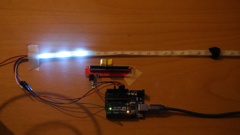
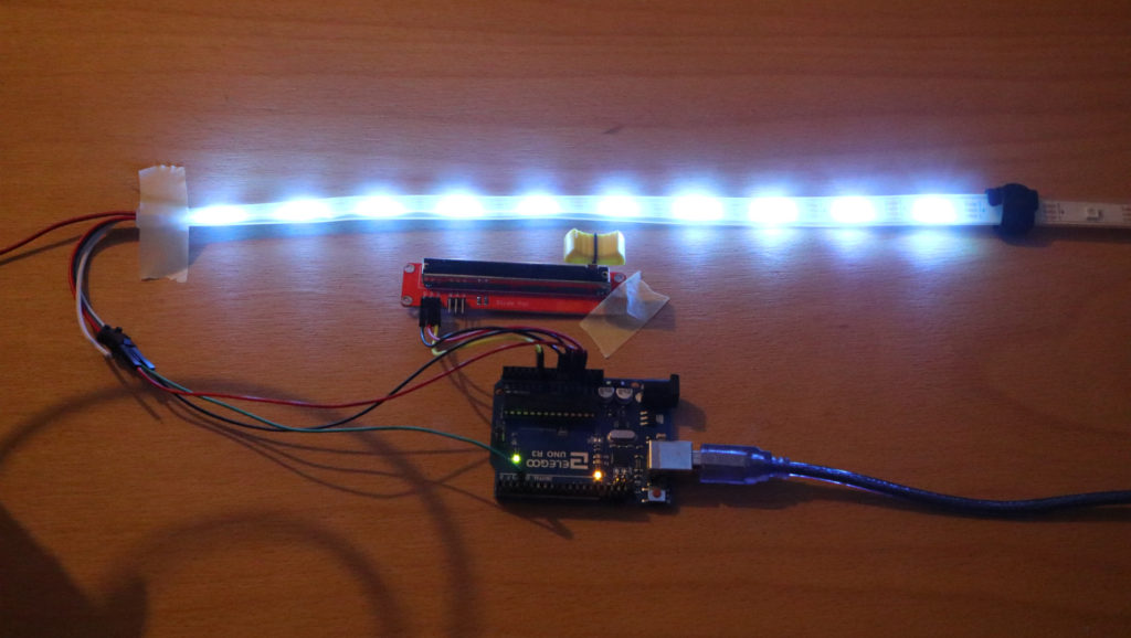
If the code is transferred to the Arduino, the LEDs should light up based on the position of the slide knob.
Slide knob at a left-middle position; 3 LEDs are switched on:
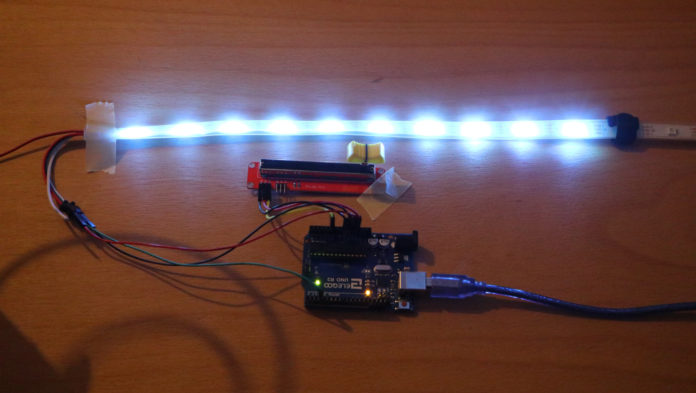
Slide knob at the most outer right position; all 10 LEDs are switched on:
hello, im kinda new with arduino, i have a gemma and was hoping to get a bit of help in what goes where, also i was wondering if it was possible to control both parameters led number and color with the same potentiometer but without a switch ?? i love your work by the way ??
Yes, this should be possible. If you take my second code example, you accomplish such an effect by adding some more lines to the for loop. Here is an example (with four different colors):
 for (int i = 0; i < num_leds_switchedon; ++i) {
 if (value_slide_pot_a > 750) {
 rgb_led[i] = CRGB::AliceBlue;
 } else if (value_slide_pot_a > 500) {
 rgb_led[i] = CRGB::Amethyst;
 } else if (value_slide_pot_a > 250) {
 rgb_led[i] = CRGB::AntiqueWhite;
 } else {
 rgb_led[i] = CRGB::DarkOrchid;
 }
 }
Hello, how is everything? I would like to know if it would be possible to use a led less close to the slide size to do this job and be functional in the same way, because I am making a mixer and I would like to use a led to represent a% of the volume
yes it is, you can find some LED strips that have a density of 144 leds per meter. If those are still to big you can buy the WS2812B LEDS individually and create your own layout. Just remember that volume is measured in a Logarithmic scale and not linear.
Hello great Arduino Tutorial, I’m new to this programing Leds and really could use some help understanding how to add a Pot for speed control on my lights going around.
the code I’m using is under website
Thank you
Thank you so much. I’m a newbie, I was using a Adafruit_NeoPixel for my Midi Controller project, I switched to this one, this is easier for me and works perfect for my LedRing.
Good evening
please could anyone do such a program but on two potentiometers and two led strips
thanks
Can you modify this code to light up a group of LEDS (for example only 3) and the position of those 3 LEDs that are “on” would track the position of the slider?
Hi love the project, would it be posable to pulse say 8 led based on frequency. I want to tune the pulses of light in sync to ARGB fans so when they are running they look like they are stationary.
hi ! nice article !
i have the SMD5050 led strip
i cant find how to do this but with this led strip and a simple 500k potentiometer
help!
great article and very useful for a project I am building for a play.
many thanks